Alright, noted. I should issue a correction: the ADC’s SNR rating theoretically limits it to 20 bits ENOB, but the THD+N rating makes it 15.5 bits. A distinction has to be made, though: ENOB is different from the output width. What says it’s a 24-bit or 32-bit sampler on the box always has a lower ENOB, so correct me if I’m wrong, but this one should be fine.
If you’re curious, the one I picked out has a max output width of 32 bits, and is the top-of-the-line “audio ADC” Texas Instruments sells:
It’s helpful to think in terms of distance. 1 ms of latency is a little over a foot of distance that sound travels in that time. If a player is standing 10 feet in front of their amp, they are playing with 10ms of latency.
It’s also helpful to think that there is a total latency budget before someone starts to notice. 10ms likely isn’t a problem, but if you use 10ms in processing and then someone stands 10 feet in front of their amp it will be 20ms and that may start to feel weird.
The most sensitive latency case is feeding a singer’s voice back into their in-ear monitors. If you have 3ms of latency in that setup, the bone conduction to their ears will be out of sync with their voice in the monitors sounding like it’s coming from 3 feet away outside their own head. That bothers singers pretty quickly. You can tell when they take their in-ear monitors out and stomp on them.
You will easily get away with 3-5ms latency and probably more if you have to.
Which is really pretty generous; 3-5ms is a lot of processing time. For comparison, to hit the standard 60fps in videogames, the total budget you have to do everything - physics, sound, enemy AI, moving everything around, drawing the whole screen multiple times, network processing, everything - is just under 17ms.
Yeah, I agree. I think it’s a complete non-issue as long as no FIR filters are used. It takes quite a bit of processing in a compiled DSP to get up to 10ms and this is fixed architecture.
Hi again Dave, interesting that you mention FIR filters; I was having a debate with an audiophile buddy about this. I pointed out that audio frontend chips (including the ADC above) often have a lot of onboard biquad filters, which are obviously second-order IIRs. He said that IIRs should be avoided because their nonlinear phase response messes with group delay; I said the IIR phase response would probably still be an upgrade from the first- or second-order bandpasses most guitar amps use for EQ.
Very nearly all audio equipment employs IIR filters at the expense of nonlinear phase. This is the tradeoff.
The only place we really see FIR filters is in processing (or processing on amps) that is designed to match a particular cabinet or speaker type. You can select the speaker from a drop down menu and it has FIR presets to start from. The tradeoff for time aligning the frequencies is delay. The lower the frequency you time align to, the more the delay. Soooo, even in amps with FIR filters, they pick some reasonable crossover point and still handle the bass with IIR.
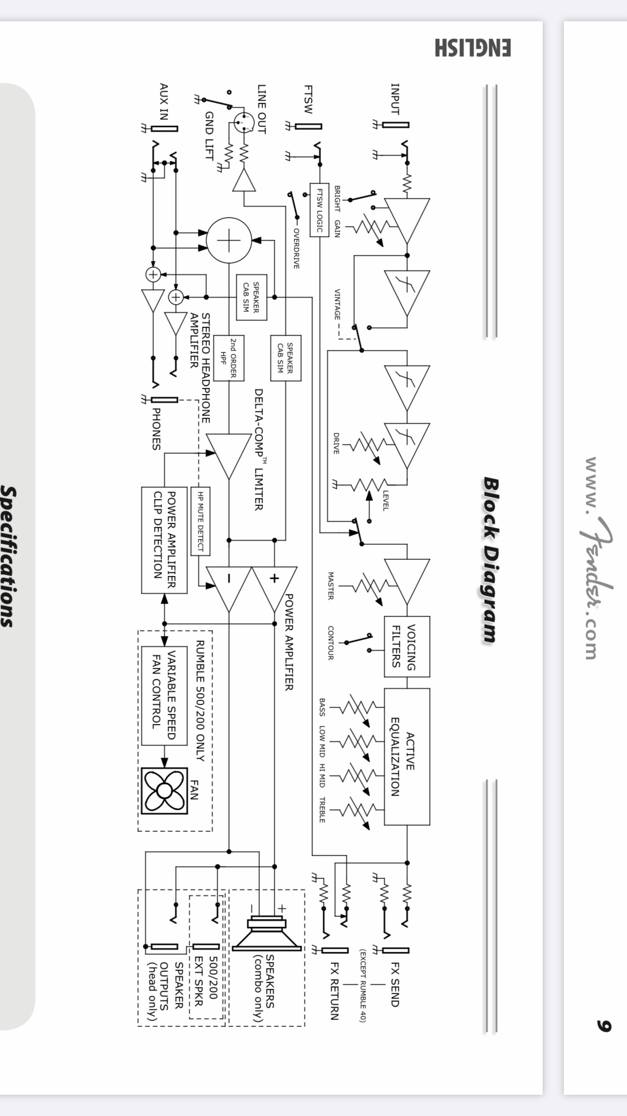
Is this to do with the “speaker cab sim” block I see on this Fender Rumble block diagram? I’m newer to the audio side of EE, but I suppose it’s important to phase-match the midrange and up when dealing with the scales inside a speaker box, so that would use an FIR filter?
Not quite. The speaker cab sim feeds the line out and headphone out. It’s supposed to simulate sounding as bad as a bass cabinet that everyone is used to hearing when listening on headphones or recording. Or as good as someone’s favorite vintage sound depending on point of view.
FIR filters for specific speakers are exactly the opposite. They erase the color of the cabinet to make it as flat as possible. You could then try to use a cab sim on top of it if you wanted to make it sound like something else. This FIR concept appears mostly in PA system design or studio monitor design. The delay of FIR isn’t as critical and a PA system is supposed to be a blank canvas. Music instrument cabinets have character that are part of the total instrument sound and people don’t pay as much attention correcting them to flat. Except for a group who are into FRFR (full range frequency response) cabinets, which is the musicians lingo for making it as flat as a PA system, also the opposite of a cab sim.
If you buy a QSC Q-Sys DSP, for example, it has speaker processing blocks in the library for all QSC loudspeakers. They implement these as FIR filters. The only tuning left to do will have to do with room and installation specific consequences.
Linea amplifiers also have an FIR DSP block available. I think these get used in listening rooms quite a bit and I’m pretty sure PMC studio monitors has FIR coefficient sets available for them.
When it comes to using creative processing to correct for more complicated loudspeaker anomalies, David Gunness is worth studying. He’s one of the more clever in the business.
"
For years, Gunness had been looking for various electronic solutions to the undesirable characteristics of horns. At EV in 1985, Gunness noticed the performance differences between various shapes of horns, and theorized that an electronic filter might allow optimization. In early 1995, EV gained access to Altec Lansing’s 1987 Acousta-CADD acoustic modeling software which revealed more loudspeaker performance characteristics than had previously been observed, but DSP programming tools were still inadequate for audio signal correction. In 2000, Greek electroacousticians John Mourjopoulos and Panagiotis ‘Panos’ Hatziantoniou described a method for smoothing precise audio analysis filters.[23] Building on this work, Gunness led a team of EAW engineers to develop a proprietary wavelet transform spectrogram for internal research. The EAW spectrogram reduced visual complexity by applying a zero-phase-shift [low-pass filter](to the audio signal under test using mirror-image [infinite impulse response]) (IIR) filters. The spectrogram revealed loudspeaker performance anomalies, allowing the engineering team to identify mechanisms they characterized as “two-port systems”; i.e. mechanisms demonstrating a single input, a single [transfer function], and a single output. Such two-port systems were of interest because they could possibly be corrected with electronic filtering. Because of their variability the methodology would not be used on any of the mechanisms which appeared to be non-linear relative to signal level, spatial distribution (“coverage”), or over time, such as cone stiffness or surround compliance. This left several substantial “linear, time-invariant” (LTI) mechanisms that would yield to correction by [digital filtering]. These included 1) time-smear from the compression driver/[phase plug] interface, 2) horn resonance, 3) cone resonance, and 4) crossover phase linearity between adjacent bandpasses. In April 2005, EAW announced the NT Series, a line of 2-way bi-amplified self-powered loudspeakers incorporating the “new technology” which was initially called “Digital Transduction Correction” (DTC). [Mix magazine quoted Gunness identifying compression driver “time smear” as a longstanding loudspeaker problem that was countered by preconditioning in the audio signal.Later that year, EAW dropped the DTC acronym and began promoting the technology as “Gunness Focusing”.
"
Returning to the slightly more mundane (and less phase-dependent) usage of digital filters for the EQ knobs, is it normal to be going with such high-order filters? The Bergantino tone controls earlier in the thread specify one EQ channel as a bandpass centered around a frequency between 40 and 150 Hz and needs to be adjusted in 5 Hz increments, so if a digital EQ is working with 48 kHz or possibly higher, that’s a very fine adjustment range for the sample rate. Application-specific, I’m imagining that a biquad IIR or 1024-point FFT just won’t cut it. Just would like to know if I’m overcompensating with filter complexity or correct, since it’s pretty much the biggest thing the central DSP has to do.
(Apologies for not directly replying to your messages, trust me when I say I hit the reply button for this one )
Hey you have a pretty good test base here. I think everyone on this forum would probably be willing to test out whatever you design and build. I know I would. If you ever wanted some user feedback, this is the right place to get it. Most of us would actually return the test prototypes back to you after the test period.
I’ve decided to connect the preamp gain knob to my DSP (not to the opamp directly), so I just want to hard-code some resistors for the input jacks. However, I’m still unclear on “best practices” with regards to how players use the gain knob vs. the instrument’s volume knob. From several bass tutorials, I’ve gathered that the bass-side volume is usually left all the way up, and the gain knob on the amp is used to adjust for clipping. However, since my gain control is effectively in software, it cannot change the analog signal or stop it from clipping, so the bass’s volume knob would have to be turned down. Is this frowned upon? What use cases does the bass’s volume knob have in a normal tube amp setup if both it and the gain knob are bookends to the same node (the instrument cable)?